A basic hydraulic circuit may seem like a messy web of lines and symbols at first. Yet, it hides a clear and orderly setup. This system uses pressurized fluid to shift or raise heavy objects with accuracy and command. The secret to getting it lies in spotting how energy moves through the setup—from the pump that builds pressure, to the cylinder that does the job, and back around. When you see that cycle, hydraulics begins to click.
What Is a Hydraulic Circuit?
A hydraulic circuit forms a web of parts built to handle mechanical jobs by passing force through squeezed liquid. Engineers and technicians use it a lot in factory machines, car setups, and tough construction gear. It shines because it packs big power into small areas.
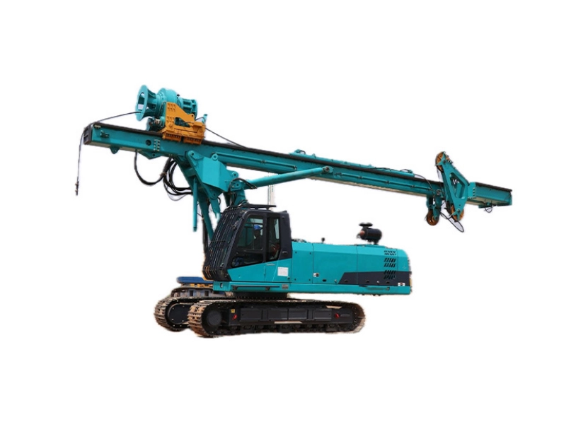
Basically, the circuit turns mechanical drive—like from an engine or motor—into hydraulic force with a pump. That force travels along tubes and valves until it hits an actuator, often a hydraulic cylinder. There, it changes back into action. This could mean hoisting a weight, squeezing sheet metal, or swinging an excavator boom. Many folks in the field rely on this everyday.
Key Components in a Simple Hydraulic System
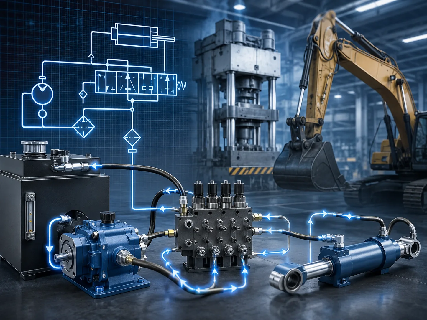
Every piece in the circuit has its own clear job to keep things running smooth:
- Hydraulic Pump: Turns mechanical drive into hydraulic movement by pushing fluid from the tank into the setup.
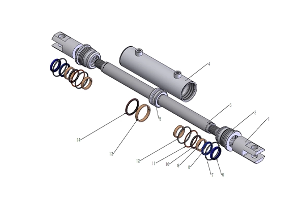
- Hydraulic Cylinder: Serves as the power, turning fluid squeeze into straight-line action.
- Control Valve: Decides where fluid goes and how much moves in the hyd circuit.
- Reservoir: Holds hydraulic oil. It lets air bubbles out, cools the returning fluid, and filters it too.
- Piping and Hoses: Link all these elements, creating a steady loop for energy shift.
If you match and care for these parts right, a straightforward hydraulic system delivers sharp precision. We see that in real-world use all the time.
How a Simple Hydraulic Circuit Works
Now that you know what each part handles on its own, tracking their teamwork during action gets simpler. Let’s break it down.
The Flow of Hydraulic Energy Step by Step
It starts with the pump pulling oil from the reservoir. The pump shoves this oil through pipes under squeeze toward the control valves. You position those valves—by hand or with electronics—and the squeezed fluid heads to one side of the cylinder’s piston.
Pressure grows on that side, and the piston pushes out for extension. Flip the valve, and flow goes to the other side for pull-back. Once motion halts, extra oil heads back via return pipes to the reservoir. There, it cools off before jumping into the loop again.
This ongoing round makes sure energy doesn’t go to waste. It either drives something or loops back for another go.
Pressure and Flow Control in Operation
To stay safe and effective, certain valves keep balance in check. Pressure relief valves pop open if squeeze goes beyond safe points. Flow control valves tweak how fast actuators shift by managing the oil amount that passes.
Keeping squeeze at the right level stops excess heat and part damage. It also ensures steady work across different weights or paces. Operators often check this to avoid surprises.
Reading a Simple Hydraulic System Diagram
Figuring out how symbols stand for real parts feels like picking up a new tongue. But after you learn it, scanning any basic hydraulic system diagram turns natural.
These drawings aren’t mere doodles. They act as standard plans that experts worldwide share. Keep that in mind as you dive in.
Understanding Symbols and Connections
Standard marks show each item:
- Pumps look like circles with arrows pointing flow direction.
- Cylinders show as boxes with rods sticking out.
- Valves appear as squares with arrows for possible flow routes.Firm lines mean work lines with squeezed fluid; dotted ones signal pilot or drain links for control cues or returns.
Spotting these shapes lets you fix issues fast, without taking gear apart. It’s a skill that saves time on the job.
Interpreting a Basic Circuit Example
Think of a setup with one cylinder and a single directional valve. That’s a classic simple case. Activate it one way, and squeezed oil enters one cylinder end to push out. Switch it, and flow flips for pull-in. After each push or pull, the returning oil drains to the reservoir, set for the next round.
This setup builds the ground for tougher circuits with several actuators or auto controls. You can build on it from there.
Common Applications of Simple Hydraulic Circuits in Machinery
Hydraulic circuits pop up in so many spots once you look—from plant floors to open fields. They manage big loads with ease and give sharp command over speed and path.
Industrial Equipment and Manufacturing Systems
In factories, hydraulics power presses that form metal, lifts that hoist pallets up, belts that slide goods along lines, and robot arms that repeat jobs. Their small size fits right into tight spots, like work cells or tool machines. Manufacturers often pick them for that reason.
Mobile Machinery and Construction Equipment
On moving gear like diggers or loaders, hydraulics supply the muscle for scooping or raising tons of dirt. Farm tractors use close systems for tilling tools or wheel turns. These circuits hold up well in dusty outdoor spots, keeping work steady in rough weather.
Hydraulic Cylinders, Made Simple
A smartly built hyd circuit does more than just shift parts. It squeezes the most from every bit of energy in the flow. At Shining Hydraulic, we tune designs so machines stay cooler, run quicker, and last longer without extra stress on pieces.
Custom Solutions for Different Applications
Machines vary in needs. Some call for slow, firm drives; others want fast power hits. Shining Hydraulic teams adjust cylinder scales, valve setups, and pipe widths to fit. This way, each system hits its goals safely, within set bounds. We tailor based on what you face, like a loader in mud or a press in a clean room.
Smart planning cuts drag inside pumps or valves. It holds steady squeeze over changing loads. Less heat means less rub on seals and longer check-ups. All this builds trust in the system over long hauls.
FAQs
Q1: What does a simple hydraulic circuit do?
It shifts mechanical energy with squeezed fluid to run actuators like cylinders for hoisting or shifting loads well.
Q2: How can I read basic symbols in a simple hydraulic system diagram?
Arrows mark flow path; boxes stand for actuators; circles usually show pumps; dotted lines signal pilot controls or drains.
Q3: Why is my hyd circuit running hot?
Too many load runs or blocked return paths often spark heat; look at filters and make sure oil paths stay open.
Q4: What maintenance should be done regularly?
Check hoses for drips, swap filters on time, track oil level and state, and confirm relief valve settings stay safe.
Q5: Can I customize my hydraulic circuit design?
Yes—scale parts and pick valves to match needed force, speed hold, accuracy, and safety edges, for top machine work.