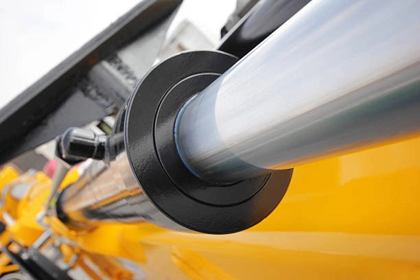
When an OEM selects hydraulic cylinder stroke length, the key measurement is not the machine’s headline travel. Stroke is the rod movement between two cylinder positions, while the mechanism’s output depends on pin locations, lever arms, and the cylinder angle at each position. Define those relationships first, then select a cylinder whose retracted length, extended length, and usable clearances fit the machine.
Record the cylinder pin-to-pin distance at the required machine positions, calculate the change, and validate the linkage in CAD or a physical layout. This prevents binding, bottoming, or insufficient end engagement.
What Does Hydraulic Cylinder Stroke Length Actually Define?
Hydraulic cylinder stroke length is the difference between the fully retracted and fully extended rod positions. In a drawing, it is separate from the retracted pin-to-pin length, the extended pin-to-pin length, and the machine’s output travel. A 400 mm stroke does not mean that a bucket, boom, or platform moves 400 mm.
The mechanism converts rod travel through its geometry. Near one end of a linkage, a small rod movement may create a large attachment movement; near a toggle position, the same movement may create little output movement while loads rise. The usable range must also leave room for cushions, stops, rod-end engagement, ports, hoses, and assembly access.
Treat stroke as one part of an envelope. The final drawing should state the retracted and extended pin centers, the intended working positions, and the clearance that remains outside the normal operating range.
How Is Hydraulic Cylinder Stroke Calculated from Machine Geometry?
How Do You Calculate Pin-to-Pin Distance?
Start with two fixed coordinates for the base pin and two coordinates for the rod-end pin: one pair at the minimum machine position and one at the maximum. For each position, calculate the pin-to-pin distance with the distance formula:
L = sqrt((x2 – x1)^2 + (y2 – y1)^2)
The required geometric stroke is the difference between the two distances. If the base pin is at (0, 0), the rod pin is at (420, 180) mm in one position, and at (260, 420) mm in the other, the distances are approximately 457 mm and 494 mm. The geometric change is therefore about 37 mm, even though the attached mechanism may move much farther at its working point.
Why Do Linkage Angles Matter through the Motion?
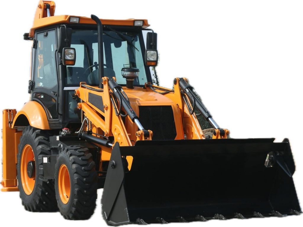
The distance calculation is a starting point, not a complete selection. The angle between the cylinder centerline and the linkage changes the output movement per millimeter and can create a near-toggle condition. Record at least the retracted, working, transition, and extended positions. For a loader, hydraulic cylinders for loader linkages should be evaluated against the bucket or arm coordinates through the entire lift, not only at the parked position.
If the mechanism uses two cylinders, calculate each side independently and confirm that frame tolerances do not force one cylinder to carry alignment load. Base the final stroke on the worst valid geometry.
Which End Clearances Should Be Added to a Cylinder Stroke?
The machine’s required travel is not automatically the cylinder’s full available stroke. Reserve only the allowances that the design actually needs:
| Clearance or Allowance | Design Question | Typical Failure When Omitted |
|---|---|---|
| Cushion zone | Does the final approach need controlled deceleration? | Impact or an unusable final portion of travel |
| Mechanical stop separation | Does the machine stop before the cylinder bottoms? | Cap or gland loading at the end position |
| Rod-end engagement | Is enough thread or bearing length retained at full extension? | Looseness, bending, or poor load transfer |
| Port and hose envelope | Can hoses bend without contacting the frame? | Chafing or restricted articulation |
| Assembly access | Can pins and retaining hardware be installed? | A workable drawing that cannot be assembled |
Adding arbitrary “extra stroke” can move the rod into an unsupported position, reduce packaging space, or let the mechanism pass a structural stop. Define an acceptance rule for both ends: every required position must be reachable with specified engagement and clearance, without internal bottoming under tolerance conditions.
How Should Stroke and Pin Locations Be Validated?
What Should a Full Motion Sweep Check?
Validate the geometry as a motion study rather than a single dimension. Sweep the linkage from the minimum to maximum machine position and inspect four items at each meaningful station: pin-to-pin length, cylinder angle, interference, and force direction. Confirm that the rod does not become the unintended guide for a misaligned bracket.
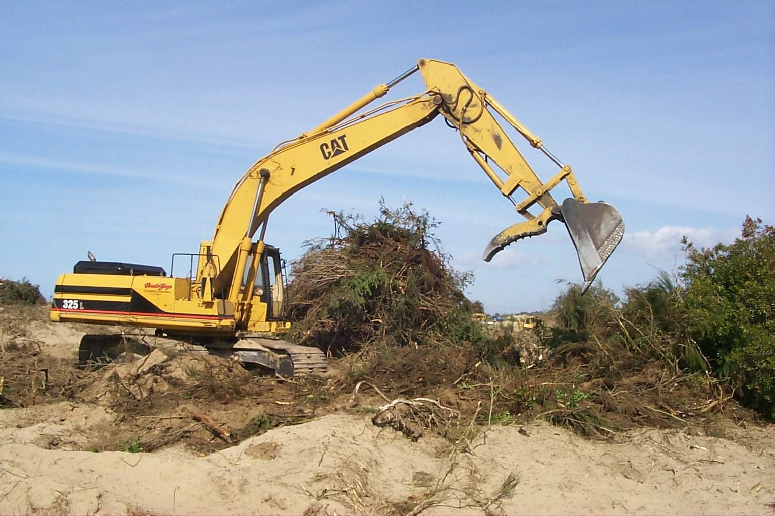
The drawing review should include pin tolerances, frame deflection, hose routing, and the position of mechanical stops. A small coordinate change can consume the clearance that looked generous in a static layout. For hydraulic cylinders for excavator boom and arm systems, review the boom, stick, and bucket positions together because one cylinder’s envelope may intersect another component during combined motion.
When Is a Physical Prototype Necessary?
Use a physical mock-up or controlled prototype when joints flex, payload changes the geometry, or the mechanism approaches a toggle. Record critical pin centers and compare them with the released drawing. An acceptance record includes minimum and maximum pin-to-pin values, end clearance, and rod-end angular range.
Which Application Conditions Change the Stroke Decision?
The same geometric method applies across equipment, but operating conditions change the tolerance for error. Loader linkages often combine changing bucket angles with high inertia. Excavator booms and sticks have broad arcs and overlapping envelopes. Scissor lifts need synchronized movement and adequate clearance as the platform rises. Agricultural implements may have repeatable end positions but large changes in payload.
Temperature, flow, load, and speed affect how quickly a cylinder reaches an end position. Hydraulic cylinders for scissor lift equipment should be checked against full platform travel and stopping behavior. Equipment category suggests questions; it does not determine stroke by itself.
FAQ
Is Hydraulic Cylinder Stroke the Same As Machine Travel?
No. Stroke is rod travel between cylinder positions. Linkage arms, pivot locations, and changing angles convert that travel into the machine’s output movement.
Should an OEM Add Extra Stroke for Safety?
Add only the clearance required by the mechanism, stops, cushions, and assembly envelope. Arbitrary extra stroke can create interference, reduce rod support, and complicate hose routing.
Why Can the Same Stroke Produce Different Machine Travel?
The cylinder angle and lever arms change through the motion. A millimeter of rod travel near one position can produce a different output movement near another position.
What Units Should Be Used in a Stroke Calculation?
Use one consistent length unit for coordinates, pin dimensions, and the distance formula. Keep that unit through the drawing release and tolerance review.
What Should an OEM Send for a Stroke Review?
Prepare the positions that define the required range, including pin coordinates or a dimensioned layout. Include working travel, retracted and extended envelopes, stop locations, rod-end engagement, port orientation, hose space, load direction, speed, and any temperature or payload range that changes the motion.
An engineering review is more useful when the intended end-of-stroke behavior is explicit: free travel to a stop, controlled deceleration, synchronized movement, or a defined mechanical position. Shining Hydraulic’s engineering service can be part of that review, and you can send the application details when the coordinates and operating conditions are ready. The result should be a clear pin-to-pin envelope and a stroke value that works across the complete machine movement.