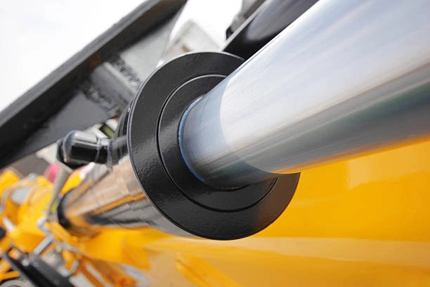
Selecting hydraulic cylinders for combine harvesters starts with the machine function, not a catalog bore. Define the moving assembly, load path, travel, speed, mounting envelope, and field conditions first. Then verify bore, rod diameter, stroke, ports, seals, and circuit compatibility against the worst operating case.
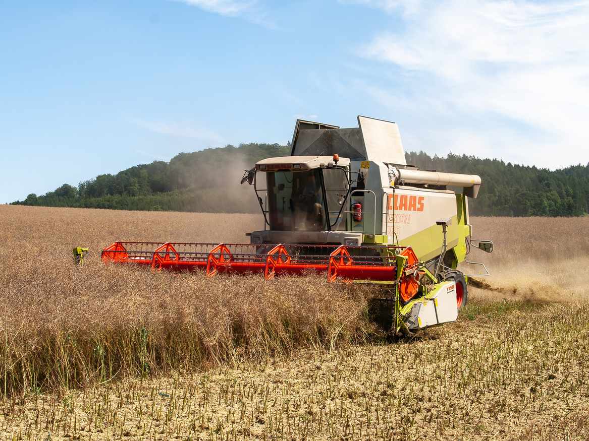
What Should a Combine Harvester Cylinder Control?
A combine may use cylinders for header height, reel position, unloading mechanisms, steering, shoe adjustment, shields, and other controlled movements. Each function creates a different design problem. A header lift cylinder may handle a high changing load through a linkage, while a reel or adjustment cylinder may need finer positioning and a different speed profile.
Start by describing the motion in mechanical terms: what moves, where the cylinder attaches, which direction the load acts, how far the assembly travels, and where the end stops are located. Then connect that motion to the hydraulic circuit. Grain harvester hydraulic cylinders are best evaluated against that complete application context, rather than selected from bore and stroke alone.
How Do You Size Bore, Rod, and Stroke for a Combine Function?
How Do You Calculate Required Cylinder Force?
The first force screen uses the relationship:
F = P × A
where F is cylinder force, P is effective pressure, and A is piston area. For extension, area is approximately πD²/4, where D is bore diameter. Retraction uses the annular area after subtracting the rod area, so extension and retraction do not produce the same force at the same pressure.
For an illustrative case, assume a cylinder sees 160 bar effective pressure and needs 80 kN extension force before linkage losses. The required piston area is 50 cm², which corresponds to an approximate 80 mm bore. This is only a first-pass example. A real design must add the linkage ratio, changing moment arm, friction, pressure margin, and the worst position in the stroke.
How Does Linkage Geometry Affect Cylinder Force?
Linkage geometry can multiply or reduce the force delivered at the attachment point. A cylinder that appears adequate at mid-stroke may be undersized when the linkage approaches a poor angle. Map the required force across the full motion, then select a rod diameter that meets column strength, side-load tolerance, and mounting requirements.
The critical point is often where the cylinder has the least favorable moment arm, not where the external load is highest. Compare the cylinder force required at several linkage positions and include dead weight, acceleration, friction, and any offset load that creates side force.
How Should Stroke and Rod Diameter Be Verified?
Stroke should cover the required machine travel without forcing the cylinder to become the end stop. Include pin-center geometry, articulation, mechanical stops, and any required cushion zone. Confirm the closed and extended lengths in the actual envelope, including hose routing and neighboring guards.
Rod diameter must also be checked against compression, unsupported length, side loading, and the mounting arrangement. A longer stroke or unfavorable retracted geometry can increase buckling risk even when the pressure-force calculation appears adequate.
Which Combine Harvester Functions Need Different Cylinder Behavior?
The function changes the specification. Use this comparison to frame the design review:
| Combine function | Primary design concern | Details to define |
|---|---|---|
| Header lift or tilt | Changing load and linkage angle | Maximum attachment load, lift geometry, end stop, and synchronization |
| Reel or gatherer adjustment | Controlled travel and repeatability | Required position range, speed, response, and available flow |
| Unloading or discharge movement | Long travel and structural reach | Stroke, extended length, load direction, and transport position |
| Shoe, screen, or internal adjustment | Compact packaging and accurate movement | Mounting space, port orientation, contamination exposure, and motion limits |
The table is a starting point, not a universal cylinder prescription. Two machines can use the same function name but impose different forces because their linkage, payload, and hydraulic pressure differ. Describe the motion profile and the consequence of overtravel before deciding whether a standard assembly is suitable.
How Do Speed, Temperature, and Contamination Affect Agricultural Machinery Cylinders?
How Does Flow Affect Cylinder Speed?
Cylinder speed follows the available flow and effective area: v = Q ÷ A. A larger bore can increase force, but it also requires more oil to move at the same speed. Check both directions of a double-acting cylinder, then review valve capacity, hose routing, port passages, and the machine’s cycle-time target.
The relevant flow is the flow that reaches the cylinder under load, after valve and hose losses. Compare extension and retraction separately because the rod-side annular area changes both speed and required flow.
How Do Temperature and Fluid Conditions Affect Selection?
Harvesting equipment operates around dust, chaff, vibration, and changing temperatures. Those conditions influence rod protection, seal and wiper selection, surface finish, port placement, and the clearance available for guards. Cold oil can increase resistance; hot oil can change viscosity and leakage behavior. Specify the operating temperature range and fluid type with the motion data.
Fluid viscosity changes the response of restrictions and seals, so a cylinder that behaves acceptably at one temperature may respond differently at another. Define the fluid grade, temperature range, and exposure conditions when selecting sealing and surface specifications.
How Should Ports and Protection Fit the Machine?
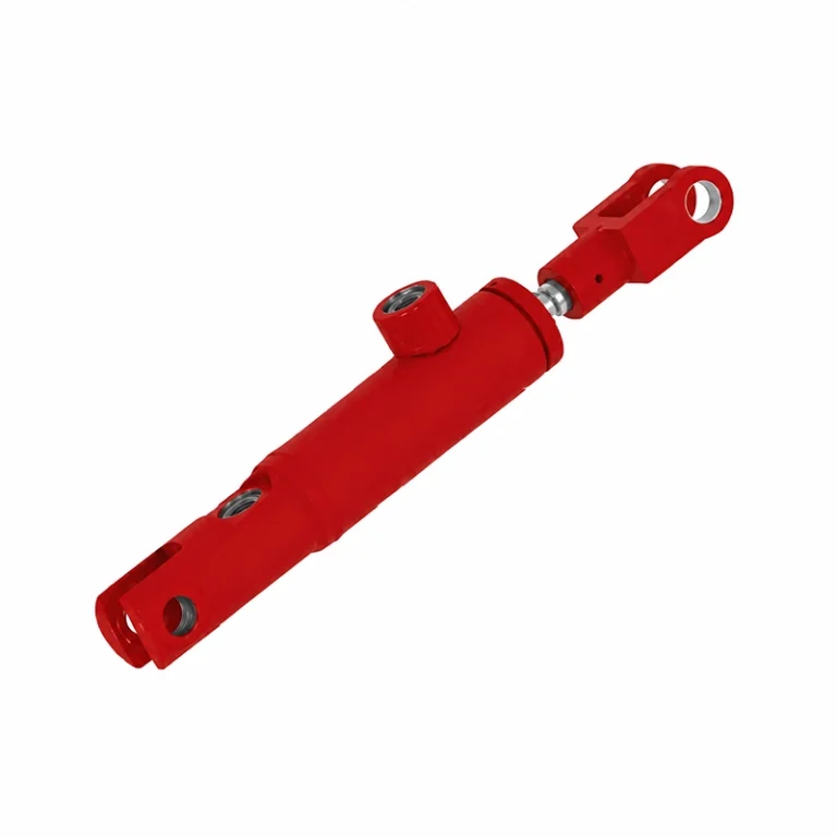
Interface details matter in a crowded machine. Confirm pin and bushing dimensions, allowable misalignment, port standard, hose bend space, and access for installation. Welded cylinders may suit compact agricultural envelopes, but the interface and duty still need to be matched to the specific combine assembly.
Place ports where hoses can flex without rubbing against guards or crop residue. Specify rod protection and wiper performance for the exposure level, while keeping the complete assembly accessible for installation and inspection.
What Should an OEM Confirm Before Releasing the Cylinder Design?
Review the design in a fixed sequence. First, verify closed and extended lengths, pin centers, articulation, end stops, and hose envelope in the machine drawing. Second, calculate the highest cylinder force and speed across realistic load cases, including unfavorable linkage angles. Third, confirm pressure, flow, temperature, fluid, porting, rod protection, and sealing requirements.
Then define the behavior the machine must achieve: travel time, synchronized movement, stopping position, acceptable drift, and any cushion or damping requirement. Match those requirements to inspection and validation evidence such as dimensional records, pressure testing, and motion checks agreed for the project. Agricultural cylinder engineering support can help organize that review before the interface is frozen.
FAQ
Is a Larger Bore Always Better for a Combine Harvester?
No. A larger bore raises available force at a given pressure, but it also increases oil demand, mass, envelope, and cost. Select the bore from the worst load case and required speed, then verify the rod and linkage.
Should Header and Unloading Cylinders Use the Same Specification?
Usually not. Their load directions, stroke profiles, duty cycles, mounting envelopes, and position requirements can differ even on the same machine. Treat each function as a separate motion and load case.
When Is a Customized Cylinder Preferable to a Standard Design?
Customization is useful when mounts, ports, stroke, envelope, sealing, or motion behavior do not fit a standard assembly. The decision should follow the interface and duty data, with common dimensions retained where they do not compromise the application.
How Does Linkage Geometry Change Required Cylinder Force?
The effective moment arm changes with angle, so the cylinder may need more force at one point in the stroke than another even when the external load is constant. Evaluate the full linkage range rather than one representative position.
How Should an OEM Validate the Cylinder Specification?
Prepare a motion drawing that shows pin centers, travel, end stops, linkage angles, and the surrounding envelope. Add load cases, effective pressure, flow range, target speed, cycle behavior, fluid and temperature range, contamination exposure, port and hose requirements, and the required stopping or positioning response.
Then send the application details for a focused technical discussion. A complete input package lets the cylinder geometry, rod strength, seals, mounting, ports, and circuit behavior be considered together. The resulting design may use a standard assembly, a modified configuration, or a customized cylinder matched to the combine’s actual motion and operating environment.