Introduction: Why Hydraulic Cylinder Design Matters in Combine Harvesters
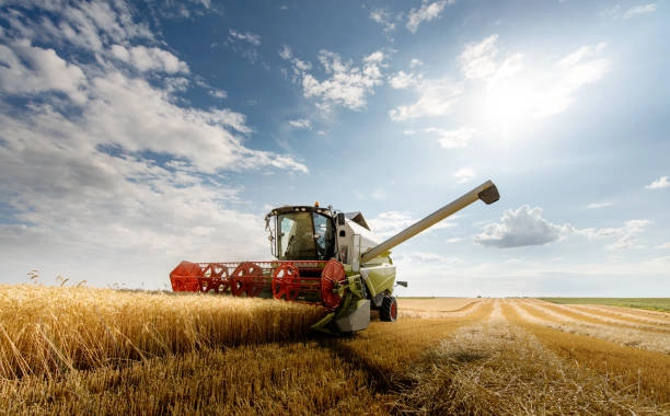
A combine harvester depends on many controlled movements. The header rises at the field edge. The reel shifts for a lodged crop. An unloading auger swings out when the grain tank is full. Hydraulic cylinders make these actions practical.
Dust and chaff get into the mechanism. Mud and temperature changes add more stress.
1. Match the Cylinder to the Required Load and Force
The starting point is force, not a catalog part number. Pushing force is broadly hydraulic pressure multiplied by piston area. Pulling force is lower because the rod occupies part of that area. Both figures belong in the calculation.
Header lifting is a useful example. Crop resistance and a rough field add dynamic load to the static weight. A sudden stop can create a pressure spike. Sizing only for the average load leaves little room for those moments.
Include a safety margin and check rod buckling on long strokes. Side loads deserve equal attention. If the linkage is out of line, the cylinder may carry damaging bending stress. Correct geometry, guides, or spherical mounting eyes prevent trouble before it reaches the seals.
2. Select the Correct Stroke Length and Installation Geometry
Stroke length defines movement. Retracted length determines whether the cylinder fits when the mechanism is folded or parked. Combine harvesters offer little spare space around the header, feeder house, and unloading system.
Check mounting points through the full movement path. A cylinder may reach both endpoints on paper and still bind at mid-stroke. Pin locations, pivot angles, and hose clearance affect the real result. A quick CAD motion study often reveals interference that a dimension sheet misses.
Different harvester models may need custom stroke lengths, ports, or pin diameters.
3. Balance Hydraulic Pressure, Flow Rate, and Operating Speed
Bore size influences force. Hydraulic flow determines rod speed. Both must work with the pump, valves, and control logic already installed.
Too much speed makes a header hit its stops and sends shock through the linkage. Too little speed frustrates the operator when ground conditions shift. The cylinder still needs suitable area and damping.
Load-holding is another concern. A raised component should not drift while the operator turns or waits to unload. Review cylinder and valve as one circuit. Treating the cylinder as isolated often produces sluggish or unstable control.
4. Protect the Cylinder from Dust, Moisture, and Corrosive Conditions
Field debris is relentless. Dust clings to an exposed rod. Chaff packs around the gland. Rain and fertilizer residue bring corrosion.
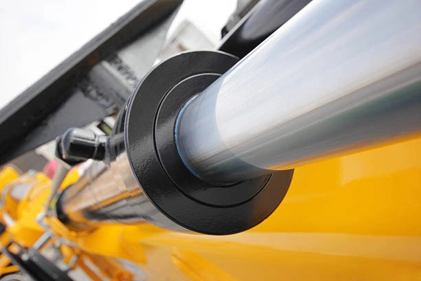
The rod surface is the first defense. A durable coating and suitable finish help seals survive repeated cycles. A small stone scratch can become a leakage path within days. Select wipers for field contamination, not a clean workshop.
Installation matters as much as material. Keep the rod away from crop impact. Provide cleaning access and avoid pockets that trap water. A humid coastal machine may need a different corrosion strategy. This is where an application-focused manufacturer adds value.
5. Choose Seals for Temperature and Contamination Resistance
Seals retain pressure and keep contaminants out. Material must match the fluid and pressure. Rod speed and temperature range matter too. A seal that works in a warm factory can stiffen during a cold spring start.
The complete package matters. Rod and piston seals do different jobs. Wipers and guide rings protect moving surfaces. Oil around the gland may indicate rod-seal wear. Internal bypass appears as slow movement or drift.
Choose seals for real duty conditions. Fluid type and cleaning chemicals provide clues. So do cycle frequency and storage habits. Generic replacements are not always economical when a machine runs hard for weeks.
6. Design for Fatigue Resistance, Vibration, and Long Service Life
Harvest season compresses a year’s workload into a short period. Cylinders cycle repeatedly over uneven ground. Vibration, pressure spikes, and impact loads accumulate as fatigue.
The barrel and rod deserve a fatigue review. Welds, the gland, piston, and mounting eyes need attention too. Material selection matters, as do alignment and manufacturing consistency. Poor weld geometry or a loose pin concentrates stress.
Early signs include a bent rod or worn pin. Fresh oil, unusual noise, or a settling component also deserve attention. Catching them during a daily inspection is cheaper than losing a harvester at peak maturity.
7. Ensure Correct Mounting and System Integration
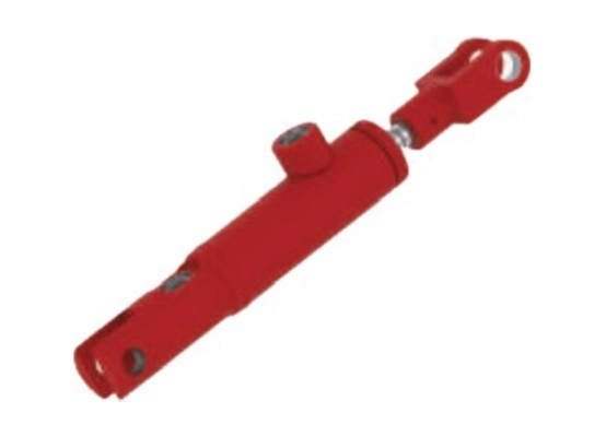
Mounting style should suit load direction and linkage. Clevis and cross-tube mounts behave differently from flange or trunnion designs. Spherical eyes can accommodate movement. A rigid mount in a misaligned mechanism turns thrust into side loading.
Check pin fit and alignment before commissioning. Review port orientation and hose routing. A hose rubbing a frame edge may fail early. Fittings must match the machine’s thread standard and pressure rating.
Compatibility extends to fluid and valves. Pump capacity and control response matter too. A replacement cylinder that changes effective area can alter speed and relief-valve behavior.
8. Use Customization and Testing to Reduce Application Risk
An OEM project may require a particular bore or stroke. Mounting footprint, coating, and seal combination may also change. Replacement programs may need the same dimensions with an updated rod finish. Review drawings and operating data early.
Useful validation covers pressure resistance and leakage. Dimensional inspection and cycle testing under representative loads add confidence. An over-bridge lifting cylinder and an unloading cylinder have different duty.
Shining Hydraulic can review drawings, samples, or an existing cylinder specification. Pressure and stroke details help define the design. Speed, mounting, fluid, and environment information support a productive discussion.
9. How to Choose a Hydraulic Cylinder Manufacturer
Look for mobile or agricultural machinery experience. Confirm support for custom dimensions and clear explanations of material, coating, and seal choices. Consistent welding and inspection matter.
The cheapest cylinder becomes expensive if it fails during harvest. Consider service life, replacement availability, and downtime alongside unit price.
Conclusion
Reliable hydraulic cylinders for combine harvesters depend on correct force sizing and geometry. Speed, sealing, environmental protection, and mounting matter as well.
Need hydraulic cylinders designed for combine harvesters or other agricultural machinery?
Contact Shining Hydraulic with your drawings, operating parameters, or existing-cylinder specifications to discuss a suitable custom solution.
FAQ
Q: What type of hydraulic cylinder is used in a combine harvester?
Combine harvesters use double-acting hydraulic cylinders for header lifting and reel adjustment. They also operate steering, covers, and unloading systems. Bore, stroke, mount, and seal package vary by function.
Q: How do I determine the correct cylinder size for a combine harvester?
Start with push and pull force plus system pressure. Check stroke, operating speed, and installation space. Include dynamic loads and inspect the linkage for side loading. A manufacturer can verify the result against the full circuit.
Q: What causes hydraulic cylinder failure in agricultural machinery?
Common causes include contaminated fluid and rod scratches. Corrosion, misalignment, side loading, worn pins, incorrect seals, and pressure spikes are also frequent. Poor hose routing can damage an otherwise sound cylinder.
Q: Can hydraulic cylinders for combine harvesters be customized?
Yes. Manufacturers can adapt bore and stroke dimensions. Mounting points, ports, rod coatings, materials, and seals can suit a specific harvester model or environment. Provide drawings or sample-cylinder measurements for a reliable quotation.