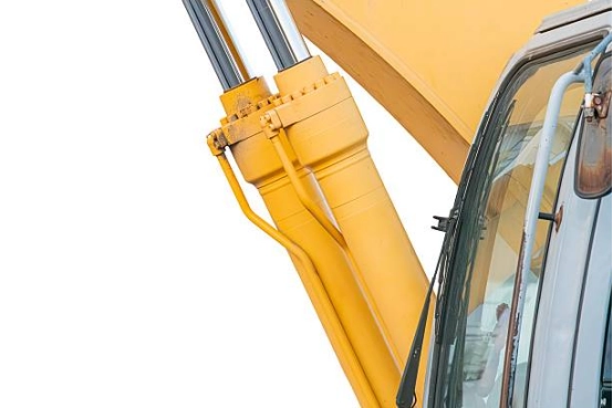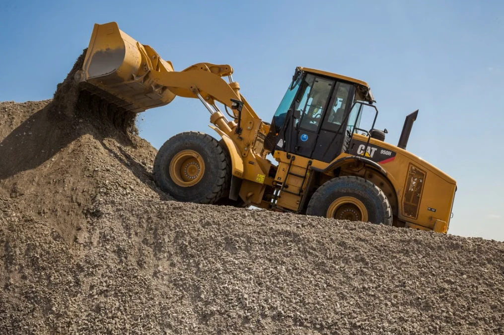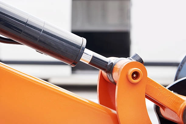
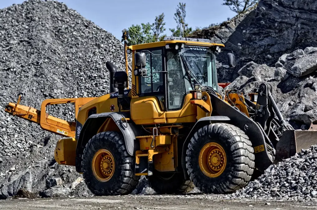
Hydraulic cylinders turn oil pressure into linear force. The formula is simple. The machine rarely is. A loader bucket changes angle during the lift, while a plow may meet compacted soil.
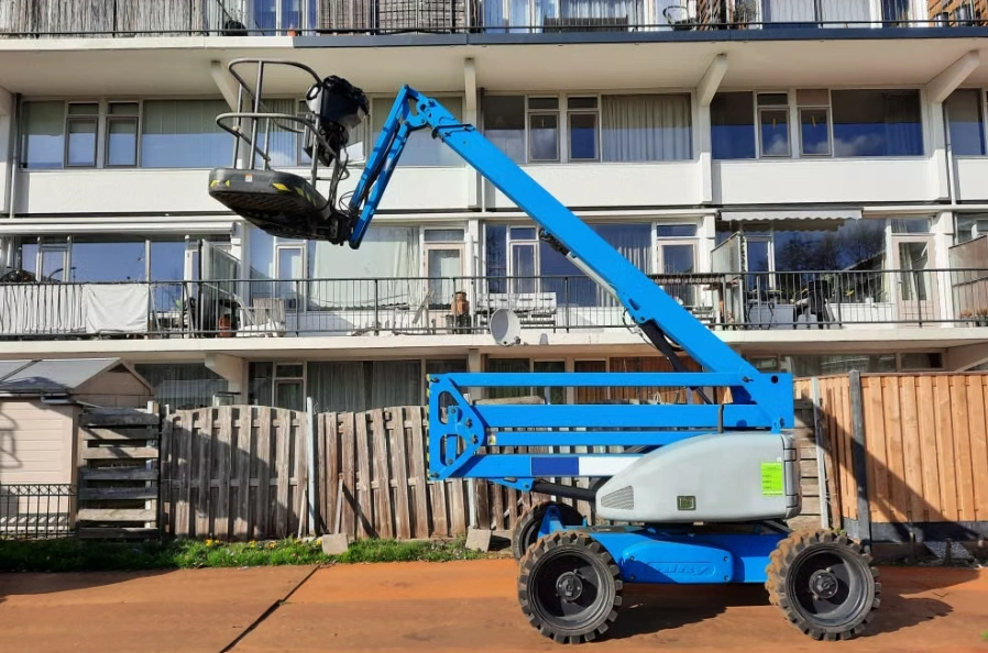
Correct force sizing prevents weak movement and wear. It gives an engineer starting point before checking linkage and duty cycle. The method applies to agricultural, construction, mining, and aerial machines.
The Basic Hydraulic Cylinder Force Formula
The core equation is:
Force = Pressure x Effective Area
F is force, P is hydraulic pressure, and A is the area exposed to pressure. Extension uses the full piston face. Retraction uses piston area minus rod area.
Pressure may be shown in bar, MPa, or psi. Area is often calculated in mm2 or in2. With pressure in N/mm2 and area in mm2, the result is newtons. Divide by 1,000 for kN.
Useful conversions: 1 MPa equals 10 bar, and 1 bar is about 14.5 psi. Friction and line losses reduce output.
What Measurements Do You Need Before Calculating?
Gather operating data before choosing a bore. A pump catalogue value is not enough.
Operating Pressure
Use pressure at the cylinder during the real load case. A system rated at 21 MPa may deliver 18 MPa at the actuator after relief settings and line losses.
Bore Diameter
The bore determines piston area. A larger bore creates more force but needs more oil and may reduce cycle speed.
Rod Diameter
Rod diameter is needed for retraction force. It affects buckling resistance and side-load tolerance. Long cylinders need a column-strength check.
Equipment Geometry
Record stroke, pin locations, linkage ratio, and cylinder angle through the movement. A cylinder can have enough calculated force and still fail when its angle becomes unfavorable.
How to Calculate Hydraulic Cylinder Extension Force
Extension uses the full piston area:
Extension Force = Pressure x pi x Bore Diameter2 / 4
Example: an 80 mm bore cylinder operates at 20 MPa.
- Piston area = pi x 80^2 / 4 = approximately 5,027 mm2.
- Extension force = 20 N/mm2 x 5,027 mm2.
- Theoretical extension force = approximately 100.5 kN.
This is piston force before friction and geometry. It may drive a lift, tip a bucket, or push a tool. Attachment force depends on the linkage.
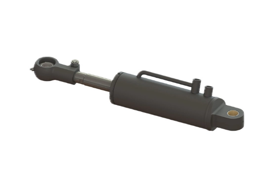
How to Calculate Hydraulic Cylinder Retraction Force
The rod occupies part of the pressure area during retraction:
Retraction Force = Pressure x pi x (Bore Diameter2 – Rod Diameter2) / 4
Use an 80 mm bore with a 45 mm rod at 20 MPa.
- Annular area = pi x (80^2 – 45^2) / 4 = approximately 3,436 mm2.
- Retraction force = 20 N/mm2 x 3,436 mm2.
- Theoretical retraction force = approximately 68.7 kN.
The difference between 100.5 kN and 68.7 kN matters for bucket return, folding implements, and clamp closing. Sticky soil can make return resistance worse.
Account for Linkage Geometry and Mechanical Advantage
Pivots and arms decide how much cylinder force reaches the working point. A useful estimate is:
Effective Equipment Force approx. Cylinder Force x Mechanical Advantage x Angle Factor
The angle factor is strongest when the cylinder pushes close to perpendicular to the lever. It falls as the cylinder and lever line up, often near the start of a lift or end of a dump cycle.
Check pin-to-pivot distances at several positions. Include attachment weight and payload. A 75 kN cylinder may work when parked and stall a few degrees into the lift. The real issue may be geometry, not pressure.
Worked Example for a Mobile Equipment Application
Consider a compact wheel loader that needs 75 kN at the bucket linkage during its hardest lift. Pressure at the cylinder is 18 MPa. Assume the linkage and hydraulic system deliver 85% of theoretical force. Apply a 1.25 design factor for variable loading.
Design force:
75 kN / 0.85 x 1.25 = approximately 110.3 kN
Required piston area:
110,300 N / 18 N/mm2 = approximately 6,128 mm2
The equivalent bore is about 88.3 mm. A practical selection might be 90 mm after confirming rod, stroke, pins, and envelope. Check buckling, brackets, welds, and impact loads. A machine test exposes what a spreadsheet misses.
Add a Safety Factor and Check Real Operating Conditions
Static payload is only one load. Digging into hard soil and driving over uneven ground create pressure spikes that can control fatigue life.
Review vibration, temperature, viscosity, side load, alignment, and pressure transients. A positioning cylinder may need a modest margin. A quarry lifting cylinder needs more.
Duty cycle matters. A cylinder suitable for ten cycles per hour may wear quickly in continuous production. Seal material, wipers, and corrosion protection matter outdoors.
Common Hydraulic Cylinder Force Calculation Mistakes
- Using pump maximum pressure instead of actual cylinder pressure.
- Forgetting rod area during retraction calculations.
- Mixing mm, m, psi, and MPa without conversion.
- Ignoring cylinder angle and lever ratio.
- Sizing for static load while the machine sees impact.
- Choosing a bore without checking rod buckling.
- Assuming a larger cylinder automatically improves speed.
Force depends mainly on pressure and area. Speed depends mainly on flow rate and effective area. A larger bore can increase force while slowing the cycle if pump flow is unchanged.
From Force Calculation to Cylinder Selection
Confirm:
- Extension and retraction force
- Bore and rod diameter
- Stroke length
- Working pressure
- Mounting style and available space
- Seal, material, and corrosion requirements
- Service life and duty cycle
- Testing requirements
Hydraulic cylinder solutions for construction machinery and agricultural equipment show how application changes the design. The installation data still determines the final cylinder.
When to Work With a Hydraulic Cylinder Manufacturer
Manufacturer support is valuable when linkage is tight, loads are dynamic, or a standard cylinder does not fit. A technical review can catch a poor mounting angle before tooling and balance bore size against speed and rod strength.
Shining Hydraulic supports consultation, cylinder development, manufacturing, inspection, and after-sales service for OEM projects.
FAQs
Q: What is the formula for hydraulic cylinder force?
Force equals hydraulic pressure multiplied by effective piston area. Extension uses full piston area. Retraction subtracts rod area.
Q: Is extension force higher than retraction force?
Yes. The rod reduces effective area during retraction, so pulling force is lower at the same pressure.
Q: How do I calculate cylinder force in kN?
Use pressure in N/mm2 and area in mm2 to obtain newtons. Divide by 1,000.
Q: Do I need to consider equipment linkage geometry?
Yes. Cylinder angle, pivot location, lever arm, and changing geometry can significantly alter force at the attachment.
Conclusion
Calculate piston area, subtract rod area for retraction, then check pressure, linkage, shock loads, and safety margin. This turns a theoretical number into a workable specification.
For help with mobile equipment hydraulic cylinders, send Shining Hydraulic the load, pressure, stroke, mounting dimensions, and operating conditions. The hydraulic cylinder sizing guide supports the initial calculation. For outdoor duty, discuss mining machinery cylinder applications with installation details ready.